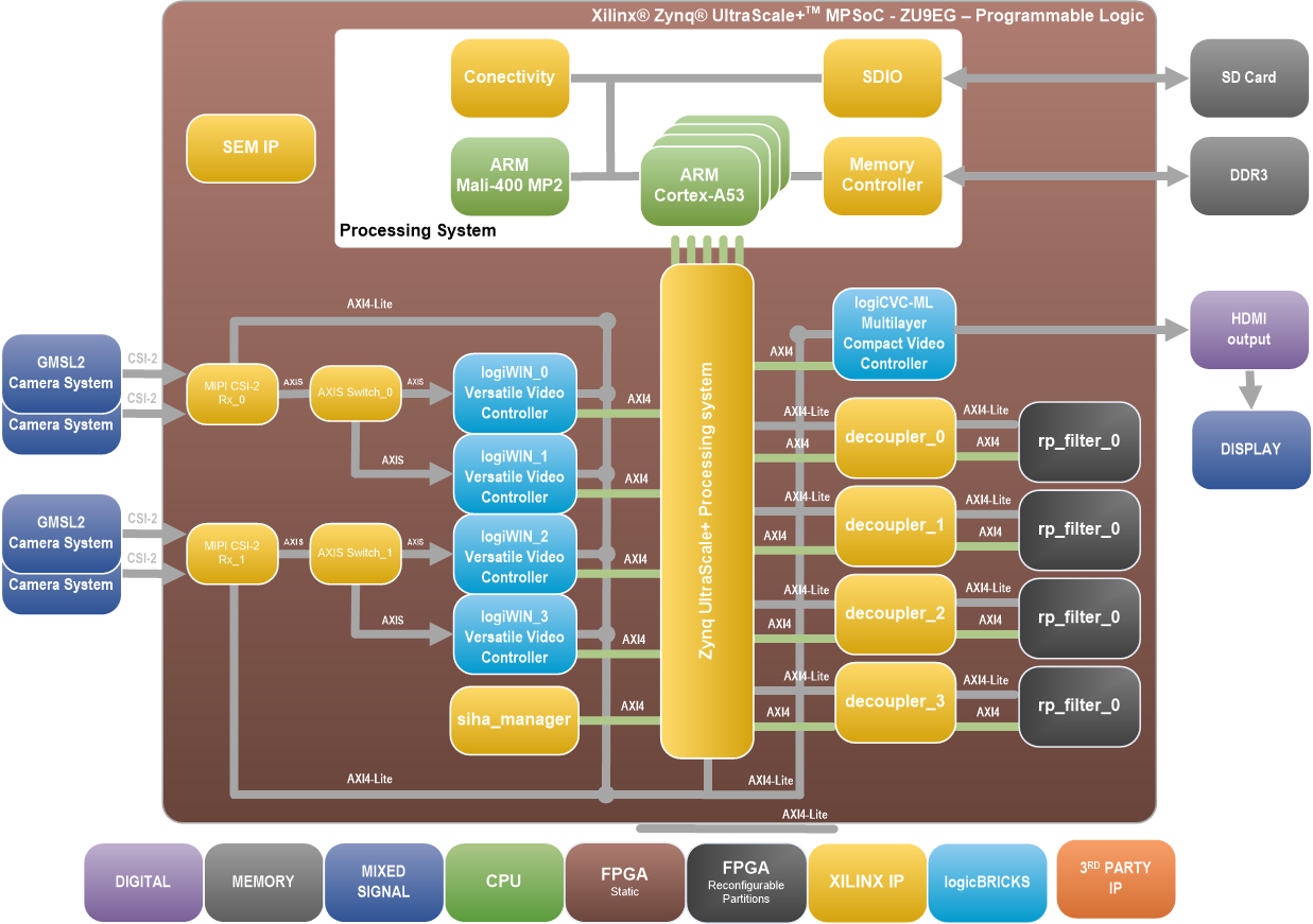
Xylon brings the complete design framework to explain and demonstrate Xilinx’s Dynamic Function eXchange (DFX). This hardware platform is optimized for embedded multi-camera vision systems. However, the demonstrated principles, techniques and design solutions can be easily adapted for different application spaces and other AMD-Xilinx programmable devices.
DFX enables features swapping by reconfiguring parts of a continually operating programmable FPGA/SoC chip. DFX is the ability to deliver new capabilities to silicon on demand, while critical functions remain running. Reconfigurable blocks of programmable logic are dynamically modified by downloading partial bit files.
Designed through the Isolation Design Flow (IDF), included fault-tolerant chip design also showcases AMD-Xilinx’s functional safety design methodologies for safety-critical applications.
This video design framework is one of the two intended for use with the Xylon logiVID-ZU Vision Development Kit users to quickly utilize the provided hardware platform for development of the AMD-Xilinx Zynq UltraScale+ MPSoC based embedded multi-camera vision systems, while getting familiar with the Dynamic Function eXchange (DFX) feature swapping of continually operating programmable FPGA/SoC chip.
The demo is based on AMD-Xilinx Zynq UltraScale+ MPSoC programmable device that processes four HD video streams from automotive cameras. Each video channel includes a reconfigurable partition that can be configured by a different video filtering modules defined by provided partial BIT files (3 per RP, total 12).
The framework includes pre-verified logicBRICKS reference designs for video capture from Xylon cameras and the display output with the RGB overlay under the Linux operating system.
Interested parties should contact Xylon via info@logicbricks.com to inquire about acquiring the logiREF-DFX-IDF Design Framework. The logiREF-DFX-IDF Design Framework works only with the logiVID-ZU-GMSL2 kit version.
|
 | logiREF-DFX-IDF Reference Design
This design implements four parallel video inputs from Xylon cameras and the display output with the RGB overlay. All video inputs are stored in the video memory, and by mean of the on board push buttons, the design user can select each of them for the full screen display output.
Video inputs are controlled by the logiWIN Versatile Video Input IP cores, and the video output is displayed by the logiCVC-ML Compact Multilayer Video Controller IP core.
|